calculator test
LC parallel Calculator

About LC Parallel Resonant Circuit Calculator
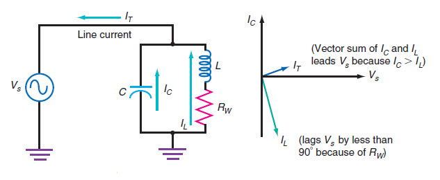
The above LC parallel resonant circuit calculator can be used to calculate the LC resonance frequency, the inductor reactance, the capacitor reactance, quality factor, series wire resistance by providing bandwidth. Also it can be used to calculate the inductor or capacitor value from given circuit LC resonance frequency and either capacitor or inductor component values. This LC parallel resonant circuit calculator is useful in the design tuned circuit for filtering and other application. One example usage is in RF circuit design that is tuned to a specific frequency. Some example usage of this online LC parallel resonant circuit calculator are as follows.
(1) How does Single Diode Modulator Circuit work? (2) Simple Amplitude Modulation (AM) circuit using Single Diode Modulato